Last Updated: 2021-09-23 06:21:32 Thursday
-- TOC --
本文尝试用多种不同的Verilog编码风格,来实现多种不同的decoder。
decoder,解码器,也叫译码器,它的逻辑功能是将每个输入的二进制代码解析成对应的高低电平信号,或者另外一个代码。比如2to4的decoder,就是对2bit所表示的数字进行解码,得到一个1-out-of-4的编码。2to4 decoder在中文教材里还被称为2线4线解码器,对应的也有3线8线解码器。这样的Decoder同样被用来在电路中做选择。
一般这种解码器,都会配上一个或多个使能位EN。这样2to4 decoder就有3个输入,4个输出。真值表如下(EN使能位,A1和A0是输入,Y[3:0]是输出):
| EN | A1 | A0 | Y3 | Y2 | Y1 | Y0 | |
|---|---|---|---|---|---|---|---|
| 0 | x | x | 0 | 0 | 0 | 0 | |
| 1 | 0 | 0 | 0 | 0 | 0 | 1 | |
| 1 | 0 | 1 | 0 | 0 | 1 | 0 | |
| 1 | 1 | 0 | 0 | 1 | 0 | 0 | |
| 1 | 1 | 1 | 1 | 0 | 0 | 0 |
本文就是用Verilog来实现类似于2to4 decoder这样的逻辑。
用结构化的Verilog代码实现。所谓结构化的Verilog代码,就是指其代码和电路图有一一对应的关系,代码中实例化的都是各种基础门电路或其他模块,用代码将电路图“画”出来。
module decoder_2to4_s(A0, A1, EN, Y0, Y1, Y2, Y3);
    input A0, A1, EN;
    output Y0, Y1, Y2, Y3;
    wire not_A0, not_A1;

    not Not1 (not_A0, A0);
    not Not2 (not_A1, A1);
    and And1 (Y0, not_A0, not_A1, EN);
    and And2 (Y1,     A0, not_A1, EN);
    and And3 (Y2, not_A0,     A1, EN);
    and And4 (Y3,     A0,     A1, EN);
endmodule
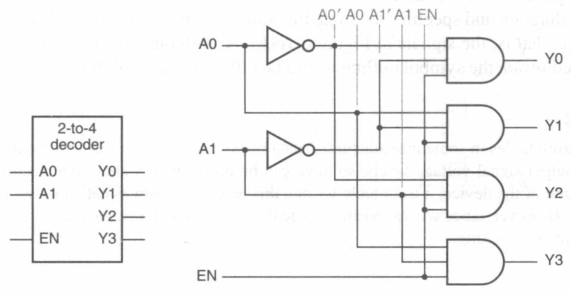
这段代码对应的电路图如下:
2个非门,4个与门,内部有两线线,structural-style verilog代码与电路图是对应的。
module decoder_2to4_d(A0, A1, EN, Y0, Y1, Y2, Y3);
    input A0, A1, EN;
    output Y0, Y1, Y2, Y3;

    assign Y0 = EN ? ({A1,A0}===2'b00) : 0;
    assign Y1 = EN ? ({A1,A0}===2'b01) : 0;
    assign Y2 = EN ? ({A1,A0}===2'b10) : 0;
    assign Y3 = EN ? ({A1,A0}===2'b11) : 0;
endmodule
Dataflow翻译过来就是数据流的意思,通过assign直接用输入端口对输出端口进行计算赋值。注意:这4个assign是同时执行,并且一直在执行,这就是硬件电路的现实。
这里使用的3个等号的 case equality,以防止比较结果出现x的情况。(但A0和A1是输入,输入有可能出现x或z的情况吗?)
module decoder_2to4_b(A0, A1, EN, Y0, Y1, Y2, Y3);
    input A0, A1, EN;
    output reg Y0, Y1, Y2, Y3;

    always @ (*)
        if (EN == 0) {Y3,Y2,Y1,Y0} = 4'b0000;
        else
            case ({A1,A0})
                2'b00: {Y3,Y2,Y1,Y0} = 4'b0001;
                2'b01: {Y3,Y2,Y1,Y0} = 4'b0010;
                2'b10: {Y3,Y2,Y1,Y0} = 4'b0100;
                2'b11: {Y3,Y2,Y1,Y0} = 4'b1000;
                default: {Y3,Y2,Y1,Y0} = 4'b0000;
            endcase
endmodule
always语句内包含的,就是我们熟悉的procedural statement,即顺序执行的语句。sensitivity list我使用了(*),表示让Verilog编译器去判断哪些值的变化需要触发always内的代码重新执行。
注意:output这里指定了reg类型,这是因为在always中要对output赋值,必须要定义为reg,否则编译错误,Illegal reference to net Y0......教科书上关于这个细节是这样说的:
A reg is not a register. Outputs like Y0 are declared as reg variables so their values can be set procedurally within an always block. But keep in mind that despite the name, a Verilog reg declaration does not create a hardware register(a set of flip-flops for storage). It simply creates an internal variable used by the simulator and the synthesizer.
module decoder_2to4_b2(A0, A1, EN, Y0, Y1, Y2, Y3);
    input A0, A1, EN;
    output reg Y0, Y1, Y2, Y3;
    reg [3:0] yy;
    integer i;

    always @ (*) begin
        yy = 4'b0000;
        if (EN == 1)
            for (i=0; i<=3; i=i+1)
                if (i == {A1,A0}) yy[i] = 1;
        {Y3,Y2,Y1,Y0} = yy;
    end
endmodule
这段代码看起来很聪明!
注意:以上代码中的for训练,看起来跟C代码一模一样,但是却不能写成i++,Verilog不支持i++语法,要到SystemVerilog才支持!
下面这段代就更聪明了!
module decoder_2to4_b3(A0, A1, EN, Y0, Y1, Y2, Y3);
    input A0, A1, EN;
    output reg Y0, Y1, Y2, Y3;
    reg [3:0] yy;

    always @ (*) begin
        yy = 4'b0000;
        if (EN == 1) yy[{A1,A0}] = 1;
        {Y3,Y2,Y1,Y0} = yy;
    end
endmodule
对以上代码,我们可以使用几乎相同的测试代码,因为这些代码定义的decoder module,input和output都是一样的。只是在测试代码中,具体实例化哪个module不一样,测试代码如下:
`include "decoder.v"
`timescale 1ns / 100ps

module test_decode();
    reg A0s, A1s, ENs;
    wire Y0s, Y1s, Y2s, Y3s;
    integer i;
    reg [3:0] expectY;

    //decoder_2to4_s UUT(A0s, A1s, ENs, Y0s, Y1s, Y2s, Y3s);
    //decoder_2to4_d UUT(A0s, A1s, ENs, Y0s, Y1s, Y2s, Y3s);
    //decoder_2to4_b UUT(A0s, A1s, ENs, Y0s, Y1s, Y2s, Y3s);
    //decoder_2to4_b2 UUT(A0s, A1s, ENs, Y0s, Y1s, Y2s, Y3s);
    decoder_2to4_b3 UUT(A0s, A1s, ENs, Y0s, Y1s, Y2s, Y3s);
    initial begin
        for (i=0; i<=7; i=i+1) begin
            {ENs, A1s, A0s} = i;
            #10;
            expectY = 4'b0000;
            if (ENs==1) expectY[{A1s,A0s}] = 1'b1;
            if ({Y3s,Y2s,Y1s,Y0s} !== expectY)
                $display("Error");
        end
        $display("Test Done");
    end
endmodule
上面5组decoder module的代码,我都放在了decoder.v文件中,因此这里include一下。测试代码中的实例化注释掉了那几行,分别是用来测试不同的module用的。Verilog的注释风格与C代码一样。(C语言的影响是很广泛的)
仿真能够看到 Test Done 的打印,看不到 Error。Wave都是一样的,如下:
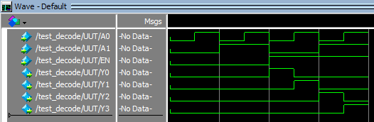
测试代码中的#10,表示延时10个ns,这个延时在wave图的时间轴上可以看到。因为timescale定义的单位就是1ns,10就是10个ns。timescale定义的100ps,表示wave图的时间轴的最小刻度。
decoder不仅仅只有2to4,还可以3to8,4to16等等。我们可以使用Verilog设计一个通用的一般化的decoder。代码如下:
module decoder_generic(A, EN, Y);
    parameter N, S;
    input [N-1:0] A;
    input EN;
    output reg [S-1:0] Y;

    always @ (*) begin
        Y = 0;
        if (EN == 1) Y[A] = 1;
    end
endmodule
跟之前代码不同之处,增加了 parameter N, S;,并且没有默认值,input和output都写成了array的形式。
下面是这个generic decoder的测试代码:
module test_decoder_generic();
    parameter N=4, S=2**N;
    reg [N-1:0] A;
    reg EN;
    wire [S-1:0] Y;
    integer i;
    reg [S-1:0] expectY;

    decoder_generic #(N,S) UUT(A, EN, Y);
    initial begin
        for (i=0; i<(2**(N+1)); i=i+1) begin
            {EN,A} = i;
            #10;
            expectY = 0;
            if (EN == 1) expectY[A] = 1;
            if (expectY != Y)
                $display("Error");
        end
        $display("Test Done!");
    end
endmodule
测试代码没有输入输出,申明的 parameter N=4, S=16; ,除了用来自己设定各种array变量外,在实例化 decoder_generic 时,通过 #(N,S) 将此参数传递给UUT模块。2**(N+1), 即 \(2^{N+1}\) 计算,使用 N+1,正好可以模拟EN=0或1的两种情况。
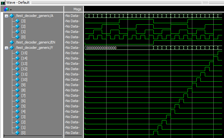
测试成功,得到的wave如下:
测试代码中的parameter, 不能用integer代替,否则会有编译错误:Range must be bounded by constant expressions. 以及:An expression for a parameter actual for the module instance ('UUT') is not constant. Parameter expressions must be constant. 似乎是说,integer是变量,而parameter是constant常量,array的range,已经给module传参,都必须是constant!
如果我们想要一个4to12的decoder,不是4to16,使用generic decoder也是可以的,测试代码修改入下:
module test_decoder_generic();
    parameter N=4, S=12;
    reg [N-1:0] A;
    reg EN;
    wire [S-1:0] Y;
    integer i;
    reg [S-1:0] expectY;

    decoder_generic #(N,S) UUT(A, EN, Y);
    initial begin
        for (i=0;i<(2**(N+1));i=i+1) begin
            {EN,A} = i;
            #10;
            expectY = 0;
            if (EN == 1) expectY[A] = 1;
            if (expectY != Y)
                $display("Error");
            $display("Pass: %d",i);
        end
        $display("Test Done!");
    end
endmodule
修改了 parameter N=4, S=12;,增加了一个过程打印 $display("Pass: %d",i);。
测试OK,i的循环从0到31,打印如下:
# Pass:           0
# Pass:           1
# Pass:           2
# Pass:           3
# Pass:           4
# Pass:           5
# Pass:           6
# Pass:           7
# Pass:           8
# Pass:           9
# Pass:          10
# Pass:          11
# Pass:          12
# Pass:          13
# Pass:          14
# Pass:          15
# Pass:          16
# Pass:          17
# Pass:          18
# Pass:          19
# Pass:          20
# Pass:          21
# Pass:          22
# Pass:          23
# Pass:          24
# Pass:          25
# Pass:          26
# Pass:          27
# Pass:          28
# Pass:          29
# Pass:          30
# Pass:          31
# Test Done!
wave如下,请注意红圈那一部分:

红圈部分表示的含义为,当 A=1100,1101,1110,1111 这4个值的时候,Y=0。这是符合4to12 decoder的,但是如何得来的呢?
关键在 expectY[A]=1 和 decoder_generic 中的 Y[A] = 1; 这两句,当 A=1100,1101,1110,1111 这4个值的时候,其实已经超出expectY和Y的index范围了,这似乎应该是个错误,但是Verilog语法是允许这样的,而且还规定了:out-of-range assignments in vectors are simply ignored! 以上代码,当这种ignore发生的时候,expectY和Y都恒为0。
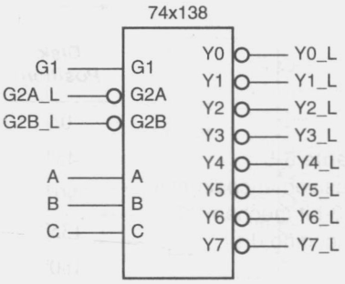
74x138是一款3to8的decoder,它有3位EN,3位INPUT,8位OUTPUT,不过OUTPUT是active_low。它的逻辑图如下:
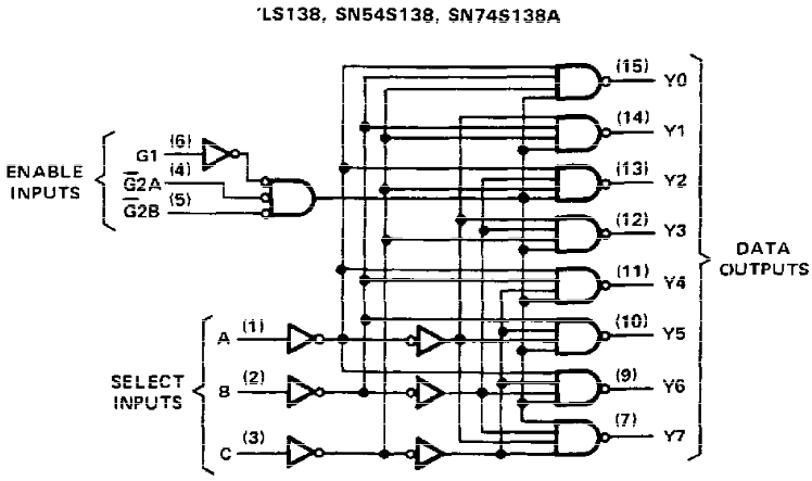
逻辑符号:
module my_74x138(G1, G2A_L, G2B_L, A, Y_L);
    input G1, G2A_L, G2B_L;
    input [2:0] A;
    output [7:0] Y_L;
    wire [7:0] Y;

    assign EN = G1 & ~G2A_L & ~G2B_L;
    assign Y_L = ~Y;
    decoder_generic #(3,8) U(.EN(EN), .A(A), .Y(Y));
endmodule
这段代码就是内嵌了一个前面写的decoder_generic。
module test_my_74x138();
    reg G1, G2A_L, G2B_L;
    reg [2:0] A;
    wire [7:0] Y_L;
    reg [7:0] expectY;
    integer i,j;

    my_74x138 UUT(G1, G2A_L, G2B_L, A, Y_L);
    initial begin
        for (i=0; i<8; i=i+1) begin
            {G1,G2A_L,G2B_L} = i;
            for (j=0; j<8; j=j+1) begin
                A = j;
                #10;
                expectY = 8'b11111111;
                if ({G1,G2A_L,G2B_L} == 3'b100) expectY[j] = 0;
                if (Y_L != expectY) $display("Error, i=%d, j=%d",i,j);
            end
        end
        $display("Test Done!");
    end
endmodule
测试代码需要遍历所有的不同输入组合,并检查输出。
测试成功,没有Error打印出来,wave图如下:
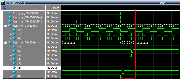
红圈部分是此3to8真正工作的区域,其它输入组合其输出是全1。
用5片74x138,可以组合成一个5to32的decoder,原理图如下:
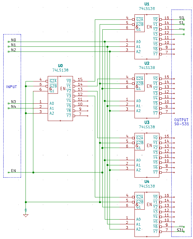
大致原理说明:用N3和N4链接U0的A0和A1,它的A2固定为0,{N3,N4}用来选择U1到U4,U0的Y0到Y3,分别接U1到U4的G2A_L,正好都是active_low;所有U0到U4的G2B_L都固定为0,G1全部接在EN上。N0,N1和N2信号,接到U1到U4的A0,A1和A2上。
显然,要实现这样的逻辑图,使用structural-style verilog可能是最合适的。
module decoder_5to32(A, EN, Y);
    input [4:0] A;
    input EN;
    output [31:0] Y;
    wire [7:0] Y0, Y1, Y2, Y3, Y4;

    assign Y = {Y4,Y3,Y2,Y1};
    my_74x138 U0(EN, 0,     0, {1'b0,A[4:3]}, Y0);
    my_74x138 U1(EN, Y0[0], 0, A[2:0],        Y1);
    my_74x138 U2(EN, Y0[1], 0, A[2:0],        Y2);
    my_74x138 U3(EN, Y0[2], 0, A[2:0],        Y3);
    my_74x138 U4(EN, Y0[3], 0, A[2:0],        Y4);
endmodule
很多时候在verilog代码中,直接使用0或1不会造成歧义,但是 {1'b0,A[4:3]} 这里,就必须使用 1'b0 ,否则编译的时候会有一个warning,告知会将这个concatenation将按照32bit来处理。
仿真测试代码如下:
module test_5to32();
    reg [4:0] A;
    reg EN;
    wire [31:0] Y;
    reg [31:0] expectY;
    integer i;

    decoder_5to32 UUT(A, EN, Y);
    initial begin
        for (i=0; i<64; i=i+1) begin
            {EN,A} = i;
            #100;
            expectY = 32'hFFFFFFFF;
            if (EN == 1) expectY[A] = 0;
            if (Y != expectY) $display("Error, i=%d", i);
        end
        $display("Test Done!");
    end
endmodule
测试基本OK,wave图如下:
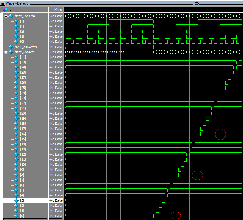
wave图中出现了3个向下的“毛刺”,原因是:N0,N1和N2这3个信号到达U1或U4的时间,早于G2A_L信号。
本文链接:https://cs.pynote.net/hd/verilog/202109181/
-- EOF --
-- MORE --